Assistive Unicycle
The year of my Master's degree was concentrated on engineering an assistive unicycle to conduct research on how humans learn complex motor functions. Unicycling might sound silly but, it closely resembles walking in terms of balance and propulsion. My prototype completed the forward propulsion system. The overarching scope of this project is to extend what we learn to exoskeletons to optimize teaching these advanced motor functions.

Project Overview
Walking and unicycling are both challenging motor tasks, they involve whole body coordination. We use unicycling to reduce the complexity of walking. Modeling unicycling, we can consider fewer degrees of freedom with continuous dynamics. Additionally, finding human subjects is simplified because of most able bodied adults are likely to have minimal unicycling experience.

Our idea evolves from creating a unicycle with motors which help with the instability of the system. Thinking of this as a 3D pendulum, we need to attach actuators to the two unstable degrees of freedom. To stabilize the Y-axis we place a motor on the unicycle forks to drive the wheel and for the X-axis, we place a reaction wheel which uses it's inertia as an external force.
MATLAB Simulations
Two 2D simulations were made to create constraints for our robot, for the frontal and lateral planes. My efforts were mainly on the lateral plane, or driving the main unicycle wheel. Using Lagrangian mechanics, we derived the dynamics of essentially a double pendulum cart. This served as an initial way to define motor constraints. We used a PID controller to have the system settle in a balanced postion
Human Subject Testing
Using Human subject testing, we were able to validate our model. Our lab has an instrumented treadmill which measures 6-driectional forces and torques on the ground (x, y, z, roll, pitch, and yaw) as well as the position of the center of mass. Using a dynamic model of the unicycle we can extrapolate the forces from the wheel from the forces on the ground. and the acceleration of the center of mass.

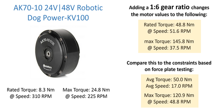
These were the results of our testing, we used these numbers to announce design constraints
Motor Selection
We wanted the device to have the capability to operate without human help. The minimum motor numbers we were looking for was a rated torque greater than 50 Nm, operating at 17 RPM; and a max torque greater than 145 Nm, operating at 37.5 RPM. From our research we couldn't find a motor significantly powerful enough within our size constraints. Our unicycle design would be used on a SUN Classic Unicycle, which needed the motor to fit between the pedal and the wheel which have a 2.5 inch clearance.

The motor we chose ended being the AK 70-10, this was based on the flat shape of the motor as well as the capabilities with a 1:6 gear ratio. Although it does not reach our exact numbers (it just reaches the average numbers but lags behind the max torque), we are expecting this to be an "assistive device" therefore it should alleviate the amount of work done by the human instead of having the full capability. Additionally this motor had a 2 inch depth which is essential for the design in order to fit inside the space reserved for the motor.
Custom Pulley
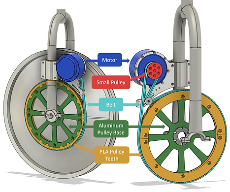
The motor could not be placed directly on the axle, so we implemented a pulley system, which also offers a degree of misalignment. This feature is beneficial since the system is designed to be easily mounted and removed from the unicycle. Additionally, the pulley allows us to achieve a 1:6 pulley ratio, helping us meet our design constraints. The base of the pulley is made from water-jetted aluminum and is bolted onto the steel hub for a sturdy connection. The pulley teeth are made from 3D-printed PLA as pulleys of the required size aren't commercially available, necessitating a custom design, if 3D printed it would be easily iterable.
Finite Element Analysis (FEA) was used to ensure the structural integrity of critical components, allowing us to predict stress points, and avoid potential failure before fabrication. For example, the pulley base was tested using a static FEA model prior to manufacturing. The results showed a factor of safety of 15, which is overkill but provides a high margin of safety. In this test, the middle bolt holes were constrained, while the outer bolt holes—where the 3D-printed pulley would connect—experienced the applied moment.


Motor Attachment

To attach the motor plate to the unicycle forks, we designed a clamp system to make it easily removable and adaptable to different unicycles. However, this approach presented some challenges due to inconsistencies between the CAD model and the real-life geometry—the CAD had simplified the forks, which were not perfectly cylindrical. To resolve this, we created a 3D-printed sleeve (shown in cyan) to wrap around the forks, ensuring a secure fit. Additionally, incorporating an alignment washer helped prevent the belt from "walking" due to misalignment.
Final Design

The final design can be seen in the following pictures and is demonstrated in the accompanying video. Unfortunately, I left the project before I could conduct rigorous testing, but the wheel was able to operate at the max RPM during preliminary trials. If I were to continue testing, I would focus on several areas. First, I would perform long-term durability tests to assess how the components hold up under continuous use. Second, I would conduct dynamic load testing to evaluate the system's performance under varying forces and real-world conditions, possibly having self balancing tests with different weights. Third, I would measure the efficiency and heat generation of the motor and pulley system during extended operation. These tests would help refine the design and optimize its functionality.